
Arindam Mallick

Machining Challenges in PTFE Components and How Manufacturers Overcome Them

Machining Challenges in PTFE Components and How Manufacturers Overcome Them

Machining Challenges in PTFE Components and How Manufacturers Overcome Them

Machining Challenges in PTFE Components and How Manufacturers Overcome Them

PTFE is widely used in industrial applications due to its excellent chemical resistance, low friction, and high temperature stability. However, machining PTFE components comes with unique challenges that differ significantly from conventional engineering plastics or metals. 

Achieving dimensional accuracy and consistent performance requires specialized machining techniques and process control.


Why PTFE Is Difficult to Machine


PTFE is soft, flexible, and highly sensitive to deformation. Unlike rigid materials, it tends to react differently during cutting and finishing operations.

Common machining challenges:

    • Material deformation during machining
    • Dimensional instability
    • Thermal expansion issues
    • Burr formation and poor edge finish
    • Difficulty maintaining tight tolerances

These factors make precision machining more complex.


1. Material Deformation


PTFE has a low modulus and can easily deform under machining pressure.

This can result in:

    • Inaccurate dimensions
    • Ovality in turned components
    • Surface inconsistencies

How manufacturers overcome it:

    • Using sharp cutting tools with optimized geometry
    • Applying controlled cutting pressure
    • Supporting components properly during machining


2. Thermal Expansion & Heat Build-Up


PTFE has a high volume of thermal expansion. Even slight temperature changes can affect dimensions.

Challenges include:

    • Expansion during machining
    • Difficulty achieving tight tolerances
    • Dimensional variation after cooling

Solutions:

    • Maintaining controlled machining temperatures
    • Allowing material stabilization before final machining
    • Using proper machining speeds and feeds


3. Maintaining Tight Tolerances


PTFE’s flexibility makes precision tolerances difficult, especially in thin wall or complex components.

This becomes critical in:

Manufacturer approach:

    • Multi stage machining processes
    • Intermediate stress relief cycles
    • Precision inspection at multiple stages


4. Burr Formation & Surface Finish Issues


PTFE can produce burrs or uneven edges during machining due to its softness. Poor surface finish may affect sealing performance and fitment.

How it is controlled:

    • High-precision tooling
    • Fine finishing operations
    • Skilled handling during post processing


5. Challenges in Filled PTFE Grades


Filled PTFE grades such as glass filled or bronze filled PTFE introduce additional machining complexity.

    • Glass filled PTFE = abrasive to tools
    • Bronze filled PTFE = higher cutting resistance
    • Carbon filled PTFE = requires optimized tooling parameters

Manufacturers often use specialized tooling and adjusted machining conditions for each grade.


Importance of Process Control


Consistent PTFE component quality depends heavily on process control.

Key focus areas:

    • Tool selection
    • Cutting parameters
    • Temperature control
    • Material conditioning
    • Final inspection and dimensional verification

A controlled machining process ensures reliable component performance in critical applications. 

Machining PTFE components requires expertise, precision, and process optimization. From dimensional instability to thermal expansion challenges, manufacturers must carefully control every stage of production. With the right machining approach and quality controls, PTFE components can deliver exceptional performance across demanding industrial applications.

[wp_comments]

Machining Challenges in PTFE Components and How Manufacturers Overcome Them Read More »

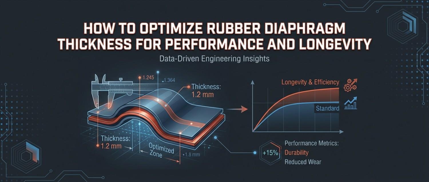
How to Optimise Rubber Diaphragm Thickness for Performance & Longevity

How to Optimise Rubber Diaphragm Thickness for Performance & Longevity

How to Optimise Rubber Diaphragm Thickness for Performance & Longevity

How to Optimise Rubber Diaphragm Thickness for Performance & Longevity

Rubber diaphragm thickness plays a critical role in determining performance, flexibility, and service life. While material selection often gets most of the attention, incorrect thickness can lead to premature failure, poor sealing, or reduced operational efficiency.

A diaphragm that is too thin may fail under pressure, while one that is too thick can reduce flexibility. Finding the right balance is key.


Why Thickness Matters


Thickness directly impacts how the diaphragm performs under operational stress.

A properly optimized diaphragm helps achieve:

    • Better flexibility during movement
    • Improved pressure handling
    • Enhanced sealing performance
    • Longer fatigue life
    • Reduced risk of tearing or rupture

Even small thickness variations can significantly affect performance in high cycle applications.


Problems with Thin Diaphragms


Thinner diaphragms offer better flexibility but may compromise durability.

Common issues include:

    • Higher risk of tearing
    • Lower pressure resistance
    • Faster material fatigue
    • Reduced lifespan in demanding applications

These are often unsuitable for heavy duty or high pressure systems.


Problems with Thick Diaphragms


Thicker diaphragms provide strength but can reduce operational efficiency.

Potential challenges:

    • Reduced flexibility
    • Higher actuation force required
    • Slower response time
    • Increased stress at flex points

Excess thickness may also affect sealing performance in dynamic applications.


Factors to Consider When Optimizing Thickness

    1. Operating Pressure

Higher pressure applications typically require thicker diaphragms for better structural support.

    1. Actuation Frequency

High cycle applications need optimized thickness to reduce fatigue failure.

    1. Material Type

Different elastomers behave differently at similar thickness levels.

For example:

      • Silicone = higher flexibility
      • EPDM = good balance
      • PTFE backed diaphragms = different structural needs
    1. Temperature Conditions

Extreme temperatures can alter flexibility and performance.

    1. Application Type

Static and dynamic applications require different thickness designs.


How Manufacturers Optimize Thickness


Reliable manufacturers often use:

    • Finite element analysis (FEA)
    • Prototype testing
    • Pressure cycle testing
    • Material performance analysis

This ensures the diaphragm performs efficiently in real world conditions.

Optimizing rubber diaphragm thickness is about balancing flexibility, strength and durability. The right thickness improves performance, reduces failures, and increases overall component life.

[wp_comments]

How to Optimise Rubber Diaphragm Thickness for Performance & Longevity Read More »

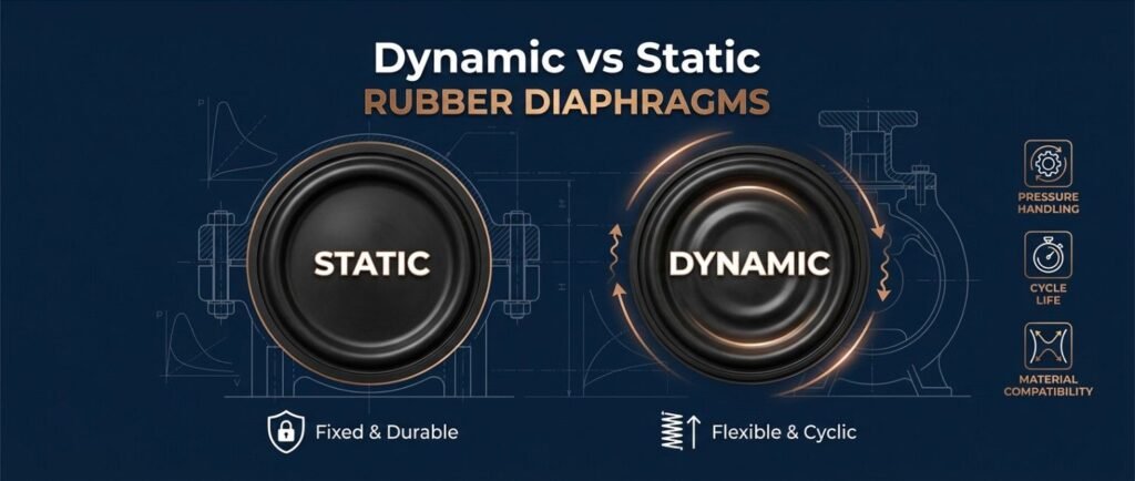
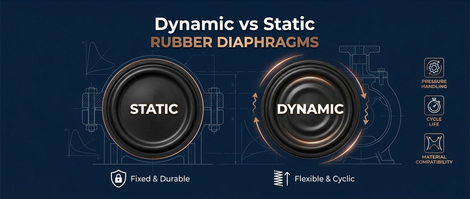
Dynamic vs Static Rubber Diaphragms: Design and Performance Differences

Dynamic vs Static Rubber Diaphragms: Design and Performance Differences

Dynamic vs Static Rubber Diaphragms: Design and Performance Differences

Dynamic vs Static Rubber Diaphragms: Design and Performance Differences

Rubber diaphragms are widely used in valves, pumps, actuators, and fluid control systems. However, not all diaphragms operate the same way. Based on application movement, they are broadly classified into dynamic diaphragms and static diaphragms.

Understanding the difference is critical for selecting the right diaphragm for performance, durability, and sealing reliability.


What Are Dynamic Rubber Diaphragms?


Dynamic diaphragms are designed for applications involving continuous movement or flexing during operation. These diaphragms repeatedly move back and forth while maintaining a seal.

Common applications

        • Pneumatic actuators
        • Metering pumps
        • Pressure regulators
        • Air operated diaphragm pumps

Design requirements

        • High flexibility
        • Excellent fatigue resistance
        • Strong tear resistance
        • Ability to handle repeated actuation cycles

Since these diaphragms experience constant movement, material fatigue becomes a major concern over time.


What Are Static Rubber Diaphragms?


Static diaphragms are used in applications where movement is minimal or occasional. Their primary function is sealing or isolation rather than continuous flexing.

Common applications

        • Static sealing assemblies
        • Pressure containment systems
        • Isolation barriers

Design requirements

        • Strong sealing performance
        • Chemical resistance
        • Dimensional stability
        • Compression resistance

These diaphragms typically face lower fatigue stress compared to dynamic variants.

Key Differences
Dynamic Diaphragms Static Diaphragms
Frequent Flexing
Minimal Movement
High Fatigue Resistance needed
High Sealing Stability needed
Focus on Elasticity
Focus on Compression Strength
Higher wear risk
Lower wear risk

Performance Considerations


When selecting between dynamic and static diaphragms, evaluate:

    • Operating pressure
    • Temperature conditions
    • Chemical exposure
    • Actuation frequency
    • Required lifecycle

Choosing the wrong type can lead to premature failure and increased maintenance costs. 

Dynamic and static rubber diaphragms serve different purposes and require different design priorities. While dynamic diaphragms focus on flexibility and fatigue resistance, static diaphragms prioritize sealing stability and chemical compatibility.

[wp_comments]

Dynamic vs Static Rubber Diaphragms: Design and Performance Differences Read More »

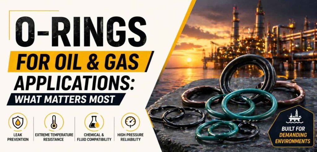
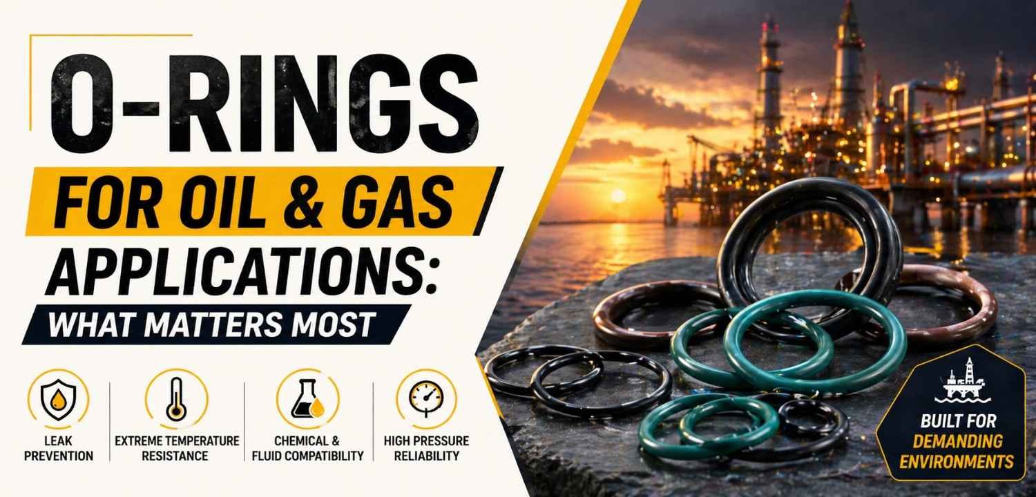
O-Rings for Oil & Gas Applications: What Matters Most

O-Rings for Oil & Gas Applications: What Matters Most

O-Rings for Oil & Gas Applications: What Matters Most

O-Rings for Oil & Gas Applications: What Matters Most

O-rings are critical sealing components in oil & gas systems, used across valves, pipelines, pumps, and drilling equipment. These environments are highly demanding, involving extreme pressures, temperatures, and aggressive media.

Choosing the right rubber O-ring is not just about size; it directly impacts reliability, safety, and system performance.


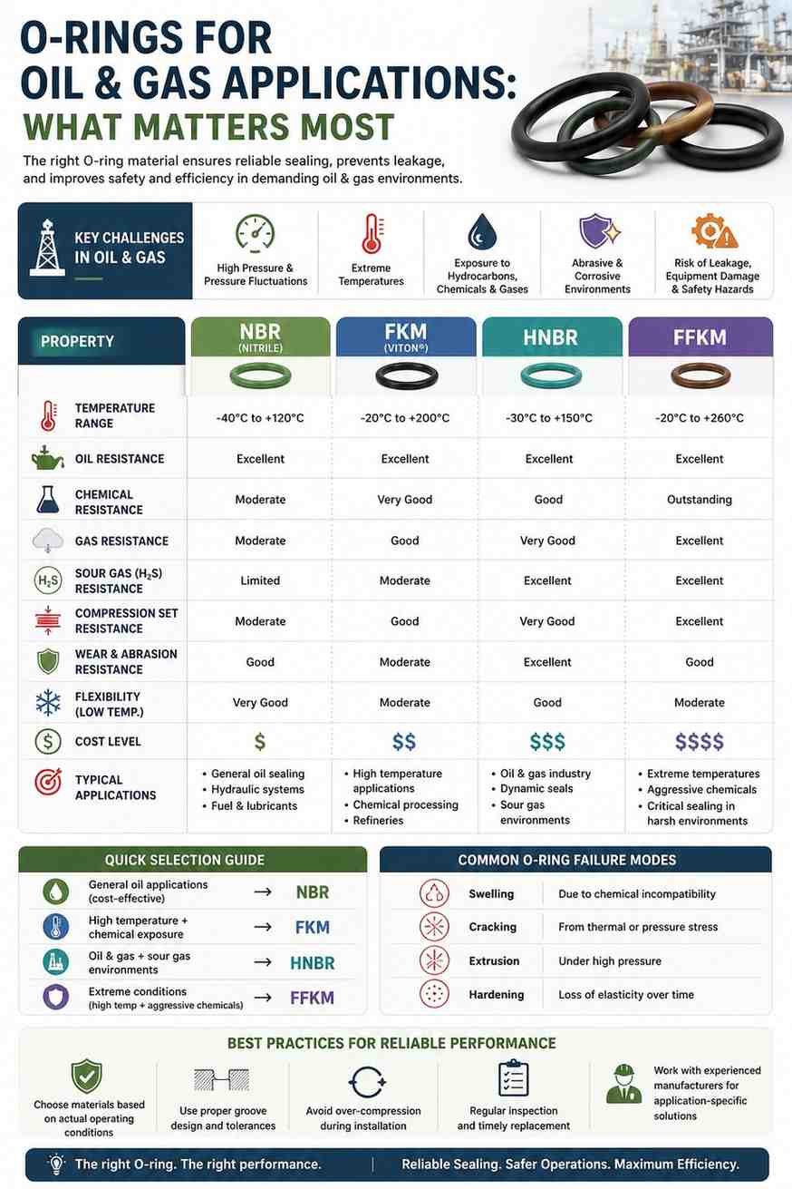
Key Challenges in Oil & Gas Applications

O-rings in this industry must withstand:

      • High pressure and pressure fluctuations
      • Extreme temperatures (both high and low)
      • Exposure to hydrocarbons, chemicals, and gases
      • Abrasive and corrosive environments

Failure in such conditions can lead to leakage, equipment damage, and safety risks.

What Matters Most in O-Ring Selection


  1. Material Compatibility

Selecting the right elastomer is critical.

      • NBR Rings (Nitrile): Good for general oil resistance
      • FKM (Viton): High temperature and chemical resistance
      • HNBR: Better mechanical strength and sour gas resistance
      • FFKM: Premium option for extreme conditions
  1. Temperature Resistance
      • Must perform across wide temperature ranges
      • Consider both continuous exposure and thermal cycling
  1. Pressure Handling
      • High pressure can cause extrusion or deformation
      • Backup rings may be required in critical applications
  1. Chemical & Gas Resistance
      • Exposure to crude oil, gases, and additives
      • Resistance to swelling, cracking, and degradation is essential
  1. Compression Set Resistance
      • O-rings must retain their shape over time
      • Poor compression set leads to sealing failure


Common Failure Modes to Watch


      • Swelling due to chemical incompatibility
      • Cracking from thermal or pressure stress
      • Extrusion under high pressure
      • Hardening or loss of elasticity

Early detection helps prevent major failures.


Best Practices for Reliable Performance


      • Choose materials based on actual operating conditions
      • Use proper groove design and tolerances
      • Avoid over-compression during installation
      • Regular inspection and timely replacement
      • Work with experienced manufacturers for application-specific solutions

In oil & gas applications, O-ring performance depends on more than just material—it’s about matching the right properties to the operating environment. Careful selection and proper installation ensure reliable sealing, reduced downtime, and improved safety.

[wp_comments]

O-Rings for Oil & Gas Applications: What Matters Most Read More »

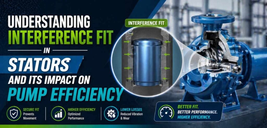
Interference Fit in Stators

Understanding Interference Fit in Stators and Its Impact on Pump Efficiency

Understanding Interference Fit in Stators and Its Impact on Pump Efficiency

Interference Fit in Stators

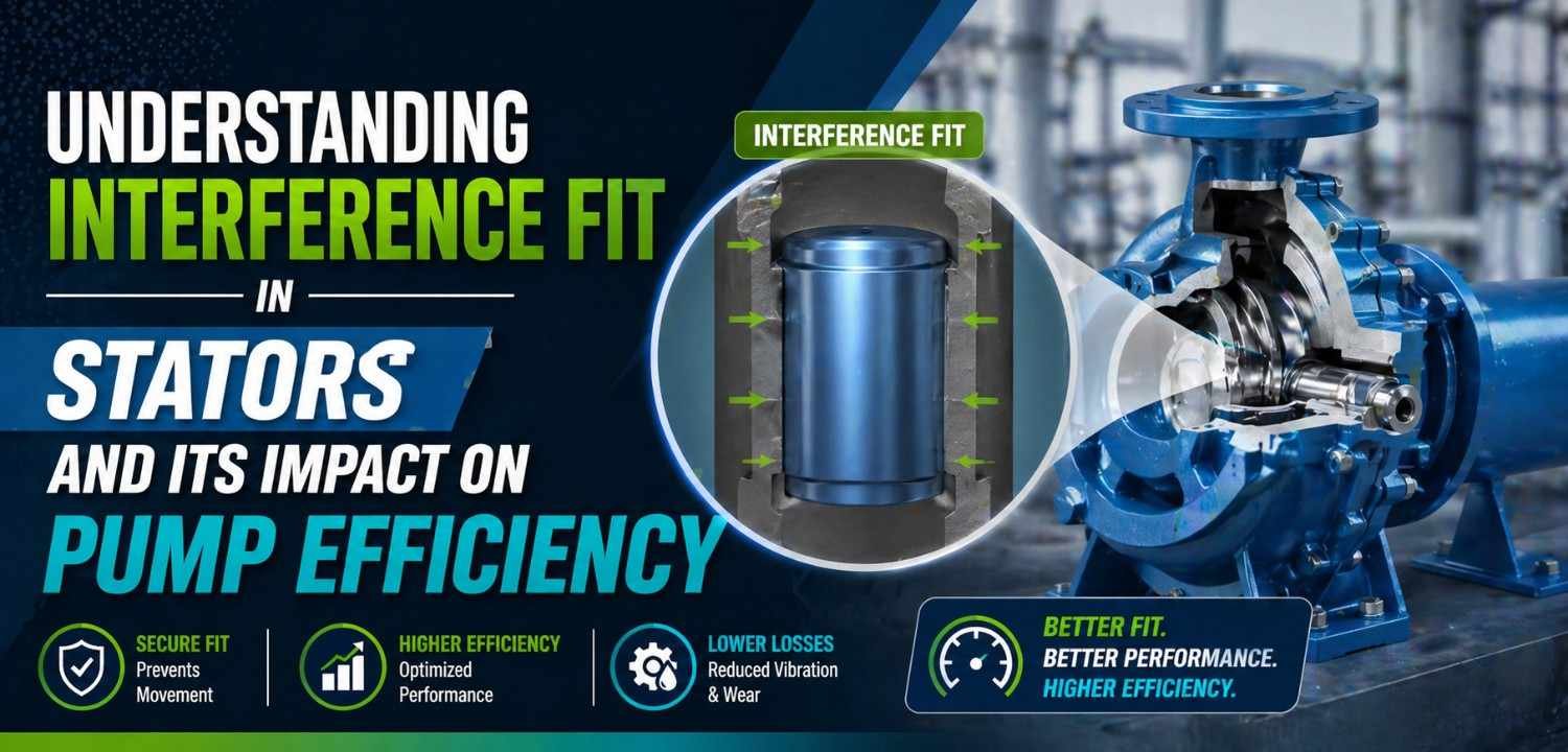
In progressing cavity pumps, the relationship between the rotor and stator is critical. One key factor that directly affects performance is the interference fit the intentional tightness between the rotor and the elastomer-lined stator.

Getting this fit right is essential for sealing efficiency, flow consistency, and overall pump performance.

What Is Interference Fit in Stators?

Interference fit refers to the controlled compression between:

This slight “tight fit” creates sealing lines that prevent fluid backflow and enable smooth cavity formation during operation.

Why Interference Fit Matters

The level of interference directly influences pump efficiency:

      • Ensures proper sealing between cavities
      • Maintains consistent flow rate
      • Reduces internal fluid leakage
      • Supports pressure generation

Without adequate interference, pump performance drops significantly.

Impact of Incorrect Interference Fit

Too Low Interference

      • Poor sealing = increased slip
      • Reduced flow and pressure output
      • Lower pump efficiency

Too High Interference

      • Excessive friction between rotor and rubber stator
      • Higher power consumption
      • Increased wear and heat generation
      • Reduced stator life


Factors Affecting Interference Fit

      • Elastomer Properties: Hardness, elasticity, and recovery behaviour
      • Operating Temperature: Expansion affects fit
      • Fluid Type: Abrasive or viscous media impact wear
      • Rotor Geometry: Precision directly impacts contact
      • Manufacturing Accuracy: Tolerances in stator molding


Optimizing Interference Fit

To achieve the right balance:

      • Select elastomers based on application conditions
      • Maintain tight manufacturing tolerances
      • Consider thermal expansion during operation
      • Test stator performance under real working conditions
      • Customize fit based on pressure and fluid characteristics

A well optimized interference fit improves both efficiency and component life.

Interference fit is a critical but often overlooked parameter in stator performance. Too little or too much interference can directly impact pump efficiency, energy consumption, and wear. Optimizing this balance ensures reliable operation, better sealing, and longer service life in progressing cavity pumps.

[wp_comments]

Understanding Interference Fit in Stators and Its Impact on Pump Efficiency Read More »

Filled PTFE Grades Explained: Glass-Filled vs Carbon-Filled vs Bronze-Filled PTFE

Filled PTFE Grades Explained: Glass-Filled vs Carbon-Filled vs Bronze-Filled PTFE

Filled PTFE Grades Explained: Glass-Filled vs Carbon-Filled vs Bronze-Filled PTFE

Filled PTFE Grades Explained: Glass-Filled vs Carbon-Filled vs Bronze-Filled PTFE

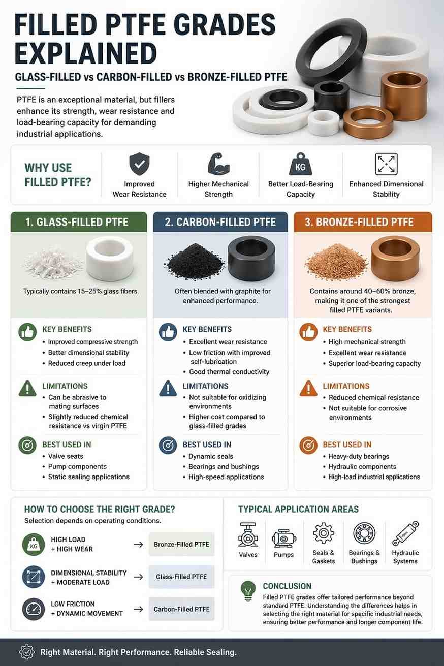
PTFE (Polytetrafluoroethylene) is widely used for its excellent chemical resistance and low friction. However, virgin PTFE has limitations such as low wear resistance and creep under load.

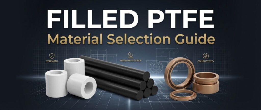
To enhance its performance, PTFE is combined with fillers like glass, carbon, and bronze—each offering distinct advantages depending on the application.

Why Use Filled PTFE?


Adding fillers improves:

  • Wear resistance
  • Mechanical strength
  • Load bearing capacity
  • Dimensional stability

This makes filled PTFE suitable for demanding industrial applications.

Filled PTFE Grades Explained: Glass-Filled vs Carbon-Filled vs Bronze-Filled PTFE

1. Glass Filled PTFE

Glass filled PTFE typically contains 15–25% glass fibres.

Benefits

  • Improved compressive strength
  • Better dimensional stability
  • Reduced creep under load

Limitations

  • Can be abrasive to mating surfaces
  • Slightly reduced chemical resistance compared to virgin PTFE

Best Used In

  • Valve seats
  • Pump components
  • Static sealing applications


2. Carbon Filled PTFE

Carbon filled PTFE is often blended with graphite for enhanced performance.

Benefits

  • Excellent wear resistance
  • Low friction with improved self lubrication
  • Good thermal conductivity

Limitations

  • Not suitable for oxidizing environments
  • Higher cost compared to glass filled grades

Best Used In

  • Dynamic seals
  • Bearings and bushings
  • High-speed applications


3. Bronze Filled PTFE

Bronze filled PTFE contains around 40–60% bronze, making it one of the strongest filled variants.

Benefits

  • High mechanical strength
  • Excellent wear resistance
  • Superior load-bearing capacity

Limitations

  • Reduced chemical resistance
  • Not suitable for corrosive environments

Best Used In

  • Heavy-duty bearings
  • Hydraulic components
  • High-load industrial applications


How to Choose the Right Grade

Selection depends on operating conditions:

  • High load + wear: Bronze filled PTFE
  • Dimensional stability + moderate load: Glass filled PTFE
  • Low friction + dynamic movement: Carbon filled PTFE

Choosing the right grade ensures better performance and longer component life.

Filled PTFE grades offer tailored performance beyond standard PTFE. Understanding the differences between glass filled, carbon filled, and bronze filled PTFE helps in selecting the right material for specific industrial requirements.

[wp_comments]

Filled PTFE Grades Explained: Glass-Filled vs Carbon-Filled vs Bronze-Filled PTFE Read More »

Surface Finish and Flange Alignment: Hidden Factors in Gasket Sealing Performance

Surface Finish and Flange Alignment: Hidden Factors in Gasket Sealing Performance

Surface Finish and Flange Alignment: Hidden Factors in Gasket Sealing Performance

Surface Finish and Flange Alignment: Hidden Factors in Gasket Sealing Performance

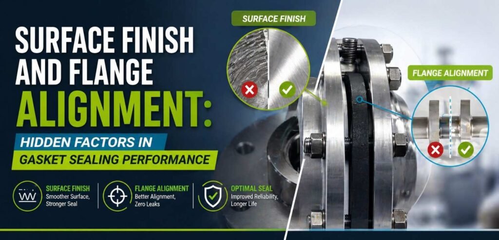
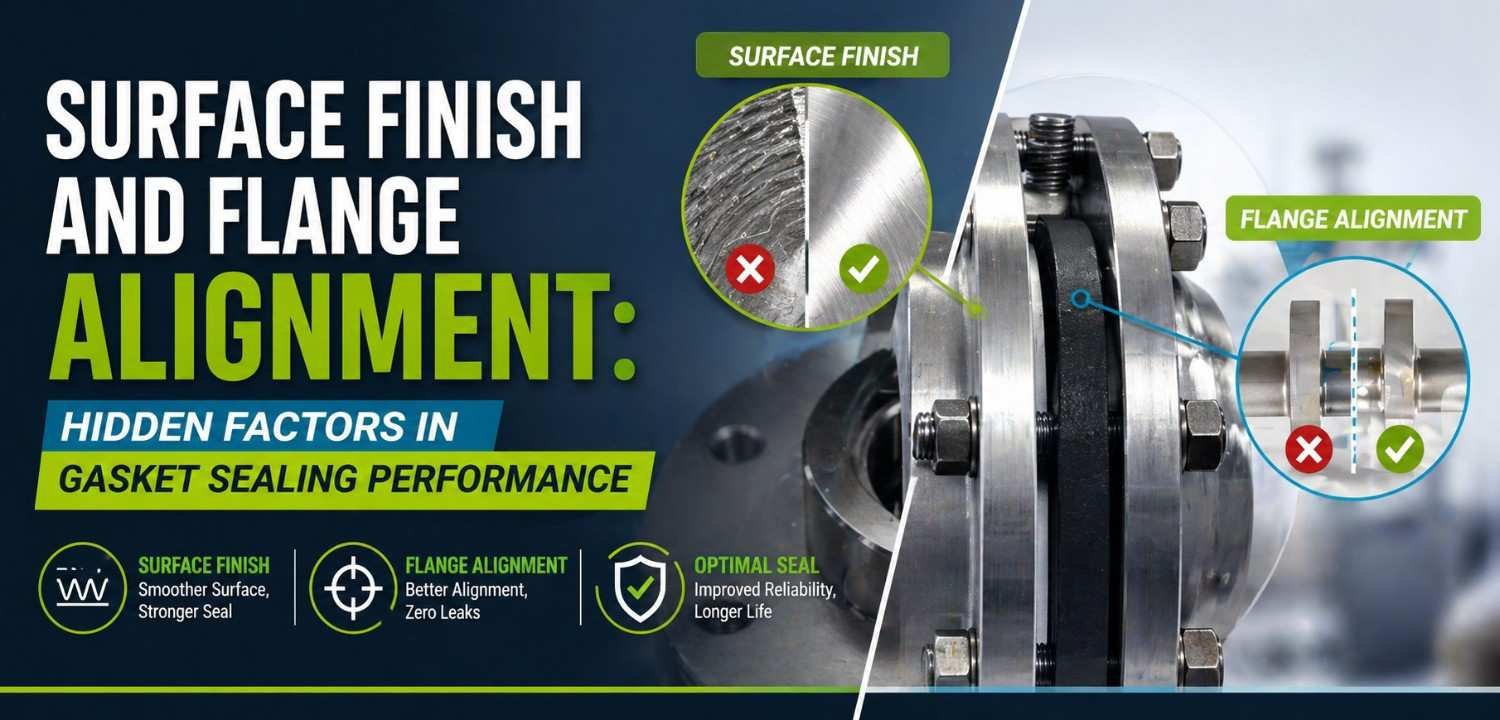
Gasket failures are often blamed on material selection or pressure conditions. However, two critical yet overlooked factors surface finish and flange alignment play a major role in sealing performance.

Even the best gasket can fail if the mating surfaces and assembly conditions are not properly controlled.

Why Surface Finish Matters


Surface finish refers to the roughness or smoothness of the flange face where the gasket sits. It directly impacts how well the gasket can conform and seal.

A balanced surface profile is essential:

  • Too rough:
    • Creates leak paths through deep grooves
    • Requires higher compression to seal effectively
  • Too smooth:
    • Reduces friction, increasing risk of gasket slippage
    • Limits the gasket’s ability to “grip” the surface

For optimal sealing, a controlled surface finish allows the gasket to deform slightly and fill micro irregularities, ensuring a tight seal.

Impact of Flange Alignment


Flange alignment is equally critical but often neglected during installation. Misalignment introduces uneven stress across the gasket surface, leading to localized failure.

Common alignment issues include:

  • Angular misalignment (tilted flanges)
  • Parallel misalignment (offset faces)
  • Uneven bolt tightening

These issues result in:

  • Uneven compression across the gasket
  • Overloading in certain areas → crushing or extrusion
  • Under-compression in other areas → leakage

Combined Effect on Sealing Performance


When poor surface finish and misalignment occur together, the risk of failure increases significantly.

  • Irregular surfaces + uneven load = incomplete sealing
  • Increased chances of leakage under pressure
  • Reduced gasket life and frequent replacements

Even high performance materials cannot compensate for poor installation conditions.

Best Practices for Reliable Sealing


To ensure consistent gasket performance:

  • Maintain recommended flange surface finish standards
  • Inspect flange faces for damage, corrosion, or irregularities
  • Ensure proper flange alignment before installation
  • Follow correct bolt tightening sequence and torque values
  • Avoid over compression or uneven loading

A well installed gasket on properly prepared surfaces can significantly improve sealing efficiency and lifespan.

Surface finish and flange alignment are often hidden but critical factors in gasket sealing performance. Ignoring them can lead to premature failures, leakage, and increased maintenance costs. Focusing on these fundamentals ensures better sealing reliability, longer gasket life, and improved system performance.

[wp_comments]

Surface Finish and Flange Alignment: Hidden Factors in Gasket Sealing Performance Read More »

Rubber & PTFE Components for Chemical Processing Plants in Europe

Supplying Rubber & PTFE Components for Chemical Processing Plants in Europe

Supplying Rubber & PTFE Components for Chemical Processing Plants in Europe

Rubber & PTFE Components for Chemical Processing Plants in Europe

Sealing Components in Chemical Plants: Common Issues Faced by European Manufacturers


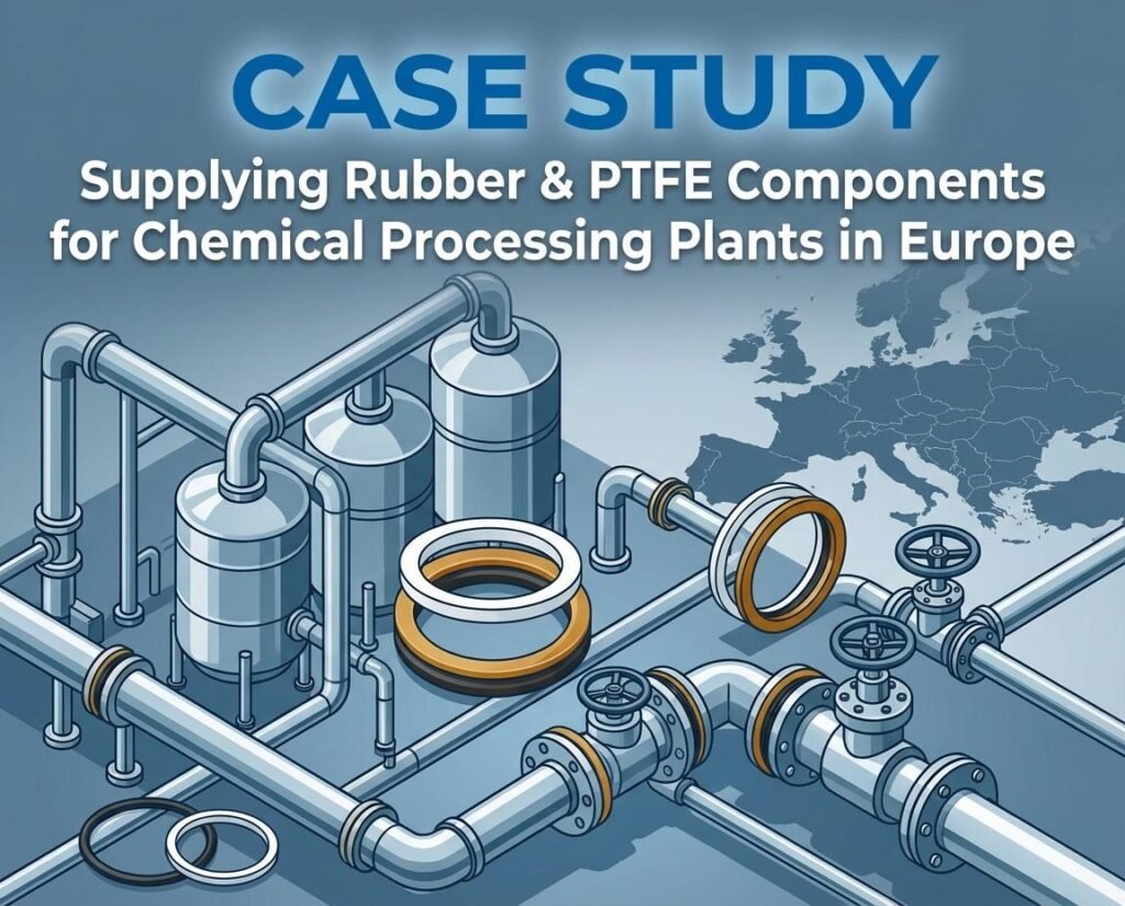
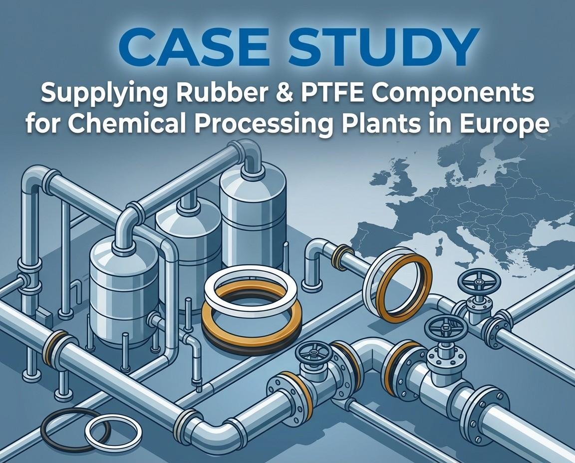
A European chemical processing company was facing frequent failures in critical sealing components used in their fluid handling systems. This resulted in premature rubber diaphragm and gasket failures, chemical attack leading to swelling and degradation, increased downtime and maintenance costs, inconsistent performance across batches. 
The company sought out a reliable rubber diaphragms manufacturer to resolve these issues. To improve system efficiency, the client opted for high-performance rubber diaphragms for pumps.


Why Rubber & PTFE Matter?: The Challenge of Sealing Components in Chemical Plants


The issue requires working with a rubber diaphragms manufacturer who meets high standards of quality and compliance. Ensuring reliable rubber diaphragms for fluid systems that can handle high-pressure and fluctuating temperatures was a top priority.

Application & Operating Conditions

    • Application: Chemical dosing systems and control valves
    • Media: Corrosive chemicals and solvents
    • Temperature Range: Moderate to high
    • Pressure Conditions: Variable with frequent fluctuations
    • Actuation: High cycle operations


Arvico’s Custom Rubber & PTFE Solutions for Chemical Plants: Tailored Components for Optimal Performance

Arvico developed customized rubber and PTFE components tailored to the application.

    • Material selection based on chemical compatibility
    • Use of PTFE faced diaphragms for enhanced resistance
    • Optimized elastomer compounds for fatigue performance
    • Custom designed diaphragms and gaskets for precise fit


Manufacturing & Quality Approach of Rubber & PTFE Components for Chemical Plants


A strong focus was placed on consistency and performance validation for rubber diaphragms and PTFE components, ensuring they met the high standards required for chemical processing systems.

    • Controlled compounding and curing processes
    • Precision molding for uniform thickness and strength
    • Multi stage quality checks (dimensional and functional)
    • Batch traceability and documentation aligned with export standards


How Arvico’s Rubber & PTFE Components Enhanced System Reliability and Reduced Failures?

    • Significant reduction in rubber diaphragm and gasket failures
    • Improved resistance to chemical attack
    • Enhanced cycle life in high frequency applications
    • Lower maintenance frequency and operational disruptions


Arvico’s High-Performance Rubber & PTFE Components: Outcome

The client achieved improved system reliability and reduced lifecycle costs. With an increased operational efficiency, reduced downtime and replacement frequency, long term partnership for continuous supply, standardization of components across multiple plants.

[wp_comments]

Supplying Rubber & PTFE Components for Chemical Processing Plants in Europe Read More »

How Actuation Cycles Impact the Life of Rubber Diaphragms

How Actuation Cycles Impact the Life of Rubber Diaphragms

How Actuation Cycles Impact the Life of Rubber Diaphragms

How Actuation Cycles Impact the Life of Rubber Diaphragms

Rubber diaphragms are designed to flex repeatedly in applications like valves, pumps, and actuators. Each movement opening and closing is known as an actuation cycle. While these components are built for flexibility, continuous cycling over time leads to wear, fatigue, and eventual failure.

Understanding how actuation cycles impact diaphragm life is essential for improving performance, reducing downtime, and selecting the right material for the application. Choosing the right diaphragm early can significantly reduce long term maintenance costs.

What Are Actuation Cycles?


An actuation cycle refers to one complete movement of the diaphragm from its neutral position to a stressed state and back. In high demand industrial systems, this can occur thousands or even millions of times.

With increasing cycles, the stress on the elastomer also increases. Over time, this directly impacts diaphragm life and performance.

  • Higher cycle count = higher cumulative mechanical stress
  • Increased stress accelerates material fatigue
  • Standard material selection may not be sufficient for high cycle use
  • Performance depends on both material and design specifications

For high cycle applications, evaluating diaphragm performance requires going beyond basic material properties.

How Repeated Cycles Lead to Failure


With every actuation cycle, the diaphragm undergoes continuous stretching and relaxation. Over time, this repeated movement leads to material fatigue, a key cause of diaphragm failure.

Initially, the damage is not visible but develops internally. Over repeated cycles:

  • Micro cracks start forming at high-stress zones (clamped edges, max flex points)
  • These cracks gradually expand, leading to tearing or rupture
  • Elasticity reduces, affecting the diaphragm’s ability to return to its original shape
  • High speed operations can generate internal heat, accelerating material degradation

This combination of fatigue, crack growth, and loss of flexibility ultimately impacts performance and lifespan.

Factors That Influence Cycle Life


Several factors determine how well a diaphragm withstands repeated actuation:

  • Material Selection: Different elastomers offer varying fatigue resistance. Choosing the right material significantly improves diaphragm life.
  • Operating Pressure: Higher pressure increases stress per cycle, reducing overall lifespan.
  • Stroke Length: Greater deformation leads to higher fatigue. Optimized design minimizes strain.
  • Temperature: Elevated temperatures and thermal cycling accelerate wear and reduce elasticity.
  • Actuation Speed: Faster cycles increase the rate of fatigue and heat build up.

Working with application specific designs can help balance these factors more effectively.

Common Signs of Cycle Induced Wear


  • Surface cracks or visible fatigue marks
  • Hardening or reduced flexibility
  • Leakage or pressure inconsistency
  • Slower or inefficient system response

Early identification of these signs can prevent unexpected system failures and downtime.

How to Improve Diaphragm Life


To extend the life of rubber diaphragms in high cycle applications:

  • Use fatigue resistant elastomers suited for cyclic loading
  • Design diaphragms to avoid excessive flexing
  • Operate within recommended pressure and temperature limits
  • Reduce unnecessary actuation frequency where possible
  • Use reinforced diaphragms for demanding applications
  • Implement routine inspection and maintenance schedules

If your application involves high frequency cycles, reviewing diaphragm design and material compatibility periodically can significantly improve performance.

[wp_comments]

How Actuation Cycles Impact the Life of Rubber Diaphragms Read More »

Failure Analysis of Rubber Diaphragms: Identifying Root Causes in Industrial Systems

Failure Analysis of Rubber Diaphragms: Identifying Root Causes in Industrial Systems

Failure Analysis of Rubber Diaphragms: Identifying Root Causes in Industrial Systems

Failure Analysis of Rubber Diaphragms: Identifying Root Causes in Industrial Systems

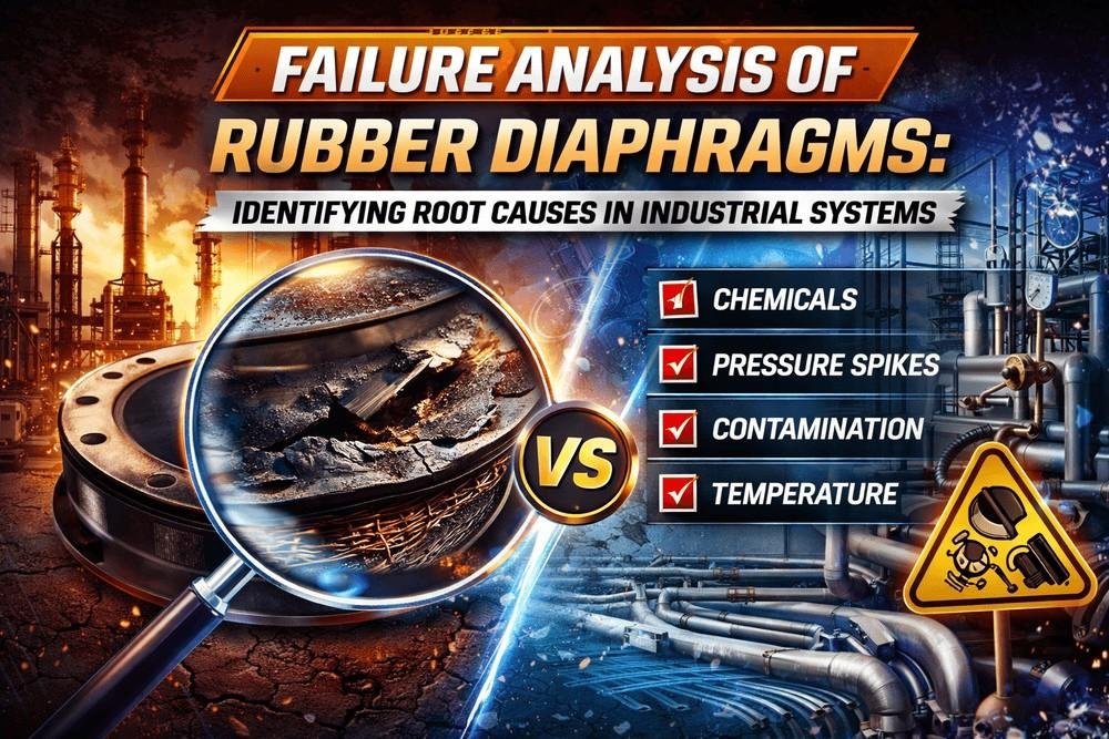
Rubber diaphragms are critical components used in valves, pumps, and actuators for sealing and pressure control. Failure of these diaphragms can lead to leakage, system inefficiency, and costly downtime. A structured failure analysis helps identify root causes and improve performance.


Common Failure Modes


      • Cracking / Hardening
        Caused by heat, ozone exposure, or aging
      • Tearing / Rupture
        Due to overpressure, fatigue, or improper installation
      • Swelling / Softening
        Result of chemical incompatibility
      • Delamination (Reinforced Diaphragms)
        Separation of layers under cyclic stress

Major Root Causes

a. Incorrect Material Selection

    • Elastomer not suitable for media or temperature
    • Leads to premature degradation

b. Excessive Mechanical Stress

    • Pressure beyond design limits
    • Frequent pressure spikes

c. Improper Installation

    • Uneven tightening or misalignment
    • Creates localized stress points

d. Thermal Degradation

    • Continuous exposure to high temperatures
    • Loss of elasticity over time

e. Chemical Attack

    • Aggressive fluids damaging polymer structure
    • Swelling or embrittlement

f. Manufacturing Defects

    • Poor curing or weak bonding
    • Internal voids or reinforcement failure


3. Failure Analysis Process


    • Visual Inspection – cracks, wear, deformation
    • Physical Testing – hardness, tensile strength
    • Chemical Analysis – media compatibility
    • Microscopic Examination – internal defects
    • Application Review – actual vs design conditions

4. Key Warning Signs


    • Leakage or pressure drop
    • Reduced flexibility
    • Surface swelling or stickiness
    • Uneven wear patterns

5. Preventive Measures


    • Select application-specific elastomers
    • Operate within pressure & temperature limits
    • Ensure correct installation practices
    • Conduct regular inspection & maintenance
    • Partner with experienced manufacturers

 Internal Link: Discover our Custom Rubber Diaphragm Solutions

Most rubber diaphragm failures are preventable. The root cause typically lies in material mismatch, incorrect operating conditions, or installation errors. A systematic failure analysis not only solves issues but enhances long-term system reliability.

[wp_comments]

Failure Analysis of Rubber Diaphragms: Identifying Root Causes in Industrial Systems Read More »